Monday, 28 May 2012

Donor Rebuild Part 1

With the chassis on order as well as the differential and brakes out for reconditioning, I have turned my attention to the suspension components. I cleaned and painted these some time ago before putting them into storage and now was the time to dust them off and start reassembly. Every serviceable part (bearings, bushes seals etc.) is being replaced so after wading through various Jaguar parts catalogues, I have procured the vast majority of required components. No doubt shortfalls will be found as I progress, but I have at least been able to make a start:

First up are the drive shafts (which also double as the upper rear 'wishbones'). These are each a 3-piece affair with universal joints connecting each section


Next up, the front uprights. When I originally disassembled these, the stub shafts were quite badly worn at the wheel bearing locations, so new ones were purchased


The front hubs get new bearings and seals along with replacement dust shields for good measure


Finally, for this update, the front upper wishbones. I have chosen to go with polyurethane bushes to replace the original rubber items from Jaguar. There is some contention on the use of these on the Cobra Club forum, but the majority of people use them, so I figure its a good starting point and it is not too onerous to replace them after the vehicle is up and running (if that ever happens!)


Tuesday, 8 May 2012

Stoneleigh 2012

Taking a break from the build (not that I have a lot from which to take a break!) I took a trip to one of the biggest kit car shows of the year. It gave me a good opportunity to look around a large number of other people's Cobras to get a better feel for some of the detail options and overall look that can be achieved starting with substantially the same shape.


There were also a few other vehicles that caught my eye. Maybe one day...


Monday, 30 April 2012

Chassis Ordered

Short post but big milestone. I visited Gardner Douglas and was made very welcome by Andy and Meena. It has been a while since I went on a 'scouting trip' whilst deciding on which kit to purchase, so I had another look around and a good discussion on the options and detail of my build. The upshot of it all is that I placed a deposit for a chassis, and I am officially in the production schedule. Roll on 8 to 10 weeks!

Monday, 26 March 2012

Driveline

With the engine substantially built (minus the induction system), I have been able to turn my attention to the transmission. When this engine is used in passenger cars and if attached to a manual transmission, the clutch is actuated by a cable. Unfortunately, this is not very Cobra friendly (especially when fitted in a right hand drive car), so the typical approach that my peers take is to fit a hydraulic conversion. Never one to take the easy route, I am working on constructing my own conversion using more readily available parts rather than rely on a £200 ‘kit’ that doesn’t really fit according to some who have used it. To this end, I needed to measure the clutch actuation force at the release (throw out) bearing to allow me to calculate the mechanical advantage and movement required at the pedal. Fortunately, we have a hydraulic press at work which, when coupled to a load cell and dial gauge, proved to be very useful for collecting the required data!


In addition, I was able to complete the fabrication of the engine cradle which allowed me to remove the engine from the build stand and access the rear of the block. This allowed the installation of the final core plug (at the end of the cam shaft) along with the oil gallery plugs.


These were followed by the block plate, flywheel and clutch which then allowed me to ‘dial in’ the bellhousing. This is achieved by fitting a dial gauge to the clutch and measuring the runout of the bellhousing location diameter when turning the crank. The bellhousing is mounted on offset dowels which can be rotated to get the runout below the 0.005” target specified by the transmission supplier.


With this completed, all that remained was to fit the transmission itself which proved to be easier than expected thanks to judicious use of my engine crane to take most of the not insignificant weight! I also fabricated a transmission support ‘foot’ at the same time as the engine cradle to allow the whole driveline assembly to be wheeled about as required. Now all it needs is a chassis around it!

Next steps involve the re-assembly of the donor suspension components for which I am currently collecting all of the new bearings, seals, shims, and fasteners. I now therefore need to switch from the UNC threads used on the engine, to the UNF threads (along with a couple of fine Metric threads for good measure) used by Jaguar in the 60’s. Hopefully I won’t get them mixed up!

Monday, 19 March 2012

Final Engine Assembly

A number of small jobs came together this weekend to see the substantial completion of the engine build (minus the intake manifold because I haven’t started making that yet!).

  • The addition of fuel injection requires a crank position signal so I have designed my own sensor mounting bracket and trigger disc target which were laser cut from steel.
  • The mounting of the trigger disc required me to turn and machine some custom spacers to put the disc in the correct location relative to the sensor as well as aligning the crank pulley with the water pump and alternator.


  • The spacers and fasteners for the alternator mounting needed modifying to suit the particular configuration of my engine which has taken some to-and-fro to get right, but this is now finally fixed.

  •  With the machining carried out on the block, along with the various aftermarket parts used, I needed to check the valve to piston clearances. This involves placing some blu-tack on the top of the piston, fitting the cylinder head and rockers then turning the engine through one complete cycle. The head is then removed and the thickness of blu-tack is measured. I had just enough, so I’m glad I didn’t go for the higher ratio rockers after all!


  • The crank sensor mounting bracket is also the timing pointer so with this finally mounted, I no longer needed access to the pistons (used to determine Top Dead Centre for fine tuning the timing pointer position) and could install the cylinder heads, rockers and covers.


The next task is to align the bellhousing and the fit the gearbox which cannot be done on the engine stand, so I have started fabricating an engine cradle. This picks up on the engine to chassis mounting points which will allow the engine assembly to sit on castors and crucially frees up the gearbox mounting bolts for adding the rest of the driveline. So far, I have tacked the structure together and test fitted the basic frame - this then needs to be fully welded and the wheels added before it can be pressed into service.


Once this is complete, I can move on to rebuilding the donor suspension components.

Monday, 23 January 2012

Engine build continues

It has been some time since my last update, mainly because it has been some time since I made any progress. However, the planets aligned this weekend and I hade the time available, the appropriate tools to hand and most importantly, the weather smiling on me so I could continue the engine build.

First task was to measure the endfloat of the camshaft and crankshaft as these values are critical for proper lubrication.


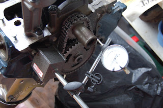
Pressing my new Dial Test Indicator (DTI) into service, I was able to check that these measurements were within specification and so could move onto ‘degreeing’ the camshaft. For those unfamiliar with the job, this means checking the cam timing against the crank angle and involves fitting an angle gauge to the crank (aligned with number 1 piston) and measuring the angle of maximum lift of the corresponding intake and exhaust tappets (lifters). These angles may not be quite as the manufacturer intended due to component tolerances of the specific engine being built and there is an amount of adjustment in the system to allow for compensation.

My cam timing came out to be around 1.5 degrees late, but since the three adjustment positions I had available it 0, +4 degrees or -4 degrees (I have not seen a vernier cam sprocket for these engines that will fit under the stock timing cover), this was a close as I was going to get! Next up was fitting the oil pump which needed modification in order for the mounting bolts to sit flat. Fortunately, the milling machine at work had been available for such a job and made light work of the task.


Fitting the oil pickup pipe finished off that part of the assembly and with one last torque check of the bolts, I could move onto closing up the oily bits of the engine.This started with the timing chain cover then the sump followed by the water pump. These were relatively simple tasks, but since I am using a random collection of original equipment, reproduction and aftermarket parts, some of the fastener kits don’t have the correct bolts so I need to purchase some additional hardware before I can finish this off.


I am now at the stage where I need to procure the parts I have designed for adding the fuel injection components before I can progress the engine build any further. I suspect it may be a little while before the planets align again, so it is not too much of a rush!

Monday, 7 November 2011

Virtual Cobra Build

With another batch of engine parts delivered, I have been progressing the block build up although missing a couple of vital items off the order means I am not as far as I could have been! Still, it gives me the chance to prepare the parts properly while I wait so I have colour matched the timing cover and water pump to the block.

In addition, I have been working on the installation of a vital part of the fuel injection system – the crank position sensor. Since the stock version of this part is prohibitively expensive to buy new and there aren’t many Mustangs in scrap yards around here, I have bought a more readily available standard component and designed a combined bracket and timing pointer along with a suitable trigger wheel.


Other ‘virtual’ progress has been around the design of the instruments and I have decided that an illumination test is required before committing to a proper PCB. I therefore need to mock up the instrument face and back lighting to ensure I have sufficient brightness to meet the Individual Vehicle Approval (IVA) test requirements. To this end I have designed a first pass circuit (which I should be able to build at work thanks to the prototype PCB facility here at work) and a ‘mask’ to direct the light. This is designed to be water jet cut along with the timing pointer components and some other instrument parts so I am aiming to group these together and procure them in the near future. Once these are in, I can build and test a number of aspects of the design before finalising the board design and getting it manufactured properly.