Tuesday, 29 March 2011

Oily and Greasy

To balance my work on the nice and clean circuit design and software writing, I decided to get some muck work under way. To this end I have started reconditioning the donor parts. The first task is to strip it all down and clean up, then protect with a suitable finish. The donor parts came from the scrap yard in major chunks which required final disassembly.


Front upright assembly as supplied from the scrap yard
After a flurry of activity with hammers, sockets and a handy press, I reduced it to its component parts:


Some people choose to grit blast and powder coat, but many use the POR15 system so I thought I would give it a try. The process requires the loose rust removing, then a good clean with 'Marine Clean' followed by a coat of 'Metal Ready' to neutralise the rust and provide a zinc phoshpate coat. Finally, two coats of POR15 and you are finished. If the parts are to be exposed to direct sunlight, a UV barrier is recommended. Since these are suspension parts, I don't need to worry about that.

I set about cleaning the rust and grease off using wire wheels and paint srtipping wheels in my drill. Once reasonably clean, I could move onto applying the POR15 system. The paint covers well and the scond coat was applied when the first was 'dry with a slight finger drag' as required by the instructions. I trialled the system on the two front lower wishbones and two front uprights:


It seems to have gone reasonably well, so I need to press on with the remaining donor parts

Oil and Grease Free

Despite my lack of updates, I have not been idle on my Cobra project. I have mostly been working on the 'cleaner' aspects of the job, concentrating on some of the electronics I will be using. First off, I finished the Megasquirt auxiliary board and since it was a two layer (top and bottom copper) layout, I have had it made by one of the many PCB prototyping houses. This was recently delivered:


A quick check in the enclosure with the vehicle connector in place:


Now all I need to do is solder it up and give it a test!

In addition, I have been developing the vehicle electrical system and have decided on at least trying to build my own electrical modules. These will cover the instruments, direction indicators and heating controls. So far I have identified the use of a Picaxe Programmable Integrated Chip (PIC) as supplied by Revolution Education. These have a simple BASIC programming laguage and are used for a whole host of projects, mostly by hobbyists. This system will allow me to control the blower and heater solenoid valve, flash the indicators and drive instrument stepper motors, and display information such as miles covered and ambient temperature. A lot of work will be required to get these moduiles up and running, but I think they will be worth it in the end.

Wednesday, 5 January 2011

Single Plane Manifold

A new year and a new set of results...

As with the dual plane manifold, I have created a CAD model that lets me simulate and analyse the air flow down individual runners of the single plane manifold:


The model was run under the same conditions as the dual plane manifold i.e. each inlet valve is opened in sequence and a pressure drop applied to approximate the piston velocity. The simulation is then interrogated for the mass flow into each cylinder. The mass flow variation against the average for each cylinder is shown below:


The average mass flow was 18% higher in the single plane manifold when compared to the dual plane design indicating that the engine would be able to breathe more easily and hence produce more power with this type of manifold (unfortunately it does not represent an 18% gain in power due to the complex flow conditions present when the engine is drawing air in sequence with the firing order, not the simple steady state conditions of the simulation). However, it can be seen that the cylinder-to-cylinder variation is still in the order of the dual plane design (-20% / +10% variation) indicating that this manifold is also not ideal for a port fuel injection application. Either manifold is suited to a carburettor or throttle body injection since the air-fuel ratio is established at the throttle plate rather than the valve.

Given the above information and a distinct lack of a readily available stock port fuel injected manifolds on this side of the pond (I didn't like the look of it much anyway!), I have decided to look at the possibility of fabricating my own. The CAD work I have done to date suggests a twin-plenum design would be the best for packaging around the known hard points. Watch this space...

Wednesday, 22 December 2010

Dual plane manifold

In parallel to the manufacture and testing of the Megasquirt controller, I have been working on the CFD analysis of options for the intake manifold. Having established my cylinder head model had at least a passing resemblance to reality in this post, I have moved on to creating a simple engine model comprising the manifold, two cylinder heads and outlet pipes representing the cylinders:


This model was then run 8 times, each with a different inlet valve being open. These were run with a constant pressure drop representing a high RPM running condition and maximum valve lift. This is the condition where runner mass flow variation will be most obvious. Once the simulations were complete, I interrogated the results and normalised them against the average mass flow for all 8 cylinders:


The chart indicates that the variation in inlet runner geometry produces quite a variation in mass flow into the different cylinders (from -11% to +15% from the average). This is not an issue with a carburettor providing the fuel because the mixing is done at the throttle plate so each cylinder gets an appropriate air fuel ratio. However, the fuel injection system will work on the total mass air flow being split evenly between the cylinders and fuel accordingly resulting in overly rich and overly lean cylinders. This is not conducive to a happy engine, so an alternative manifold is required. Onto the single plane design then...

Megasquirt Aux Board

I have now installed the output stage comprising the injector, fuel pump and Air Bypass Valve (ABV) drivers and this marks the completion of the base Megasquirt controller. However, the extras I am adding (Automotive connector, 2 coil pack wasted spark control, radiator fan control, tachometer output pulse, 2nd Exhaust Gas Oxygen sensor input, and 'engine running' signal) require an additional circuit board. I have tracked down what appears to be a relatively easy to set up and use PCB generation tool called Designspark. So far I have created the auxiliary board schematic:


Which then allowed me to create the PCB layout:


There are still a couple of details I need to sort out such as the flyback diodes for the relay driver and ABV, but I should be in a position to send this board for manufacture shortly. Before I do though, I would like to prototype some of the circuits just to make sure it will all work as planned!

Friday, 10 December 2010

Megasquirt Episode 3 - Revenge of the Sith

Progress has continued on the engine controller with the construction of the power stage with the required testing showing volts where they need to be and no volts where they shouldn't. Since I am not using the standard Megasquirt DB-37 connector, I am having to temporarily connect using discrete wires. Ultimately these will to be replaced with a flying lead to the auxiliary board containing the additional components for the wasted spark coil drive, tachometer output signal and the second exhaust gas oxygen (EGO) conditioning circuit.


The communication components are added next and checked for correct function thorough the programming connector.


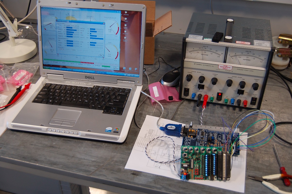
With the board working according to the instructions, I was able to move onto the input conditioning circuits which take the engine sensor data and feed it into the main processor inputs. With these components in place, I could hook it up the the laptop and run the Megatune software used for communicating with, and tuning the ECU.


The engine sensors are replicated by the Stimulator so the pots can be twiddled and the corresponding reading on the real time display changes. So far so good...

Thursday, 2 December 2010

MegaStart - The Sequel

Following successful testing of the JimStim (well, making sure there was 12V where it should be and resistances change with twiddling the pots) I made a start on building the Megasquirt module proper. The comprehensive kit from DIY Autotune comes extremely well packaged and labelled, identifying each component, its value and important assembly information such as leg bend length and if the part needs to stand off from the PCB. I would heartily recommend this company to anyone considering the purchase of a kit, or indeed anything related. Anyway, I had to make a start on this:


First job was a modification (I can't do anything the conventional way!). I am planning to use wasted spark, PWM Idle valve control, ECU controlled cooling fan relay and an 'engine running' signal, so it seemed logical to have an auxiliary PCB to tidy everything up. In addition, I am not keen on soldering wires into connectors for automotive applications since there is a risk, albeit small, of wire breakage from fatigue. The standard solder bucket DB37 connector will have to be replaced with an automotive spec crimped terminal part. I managed to stumble across an enclosure of similar footprint, but taller to allow all of the additions to be made so I procured it from Maplin (part number N85AL) and set about scheming the design. Fortunately, the enclosure manufacturer kindly makes 3D CAD models available, so this was a relatively easy job:


With this complete, I could make a start on trying to turn it into reality. Since the enclosure is metric (100mm wide slot opening) and the Megasquirt PCB is imperial (4 inches), I had a small amount of filing to get the two to mate together. This had to be done with great care to ensure the intermediate copper layers (it is a 4 layer PCB) were not shorted to the case. All appeared to be well:


This has a knock-on effect to the heatsink strip that sits under the power devices. I had to shave a small amount off this as well to get the holes to line up:


With this all fitting together, I can make a start on stage 1 of the controller - the power supply.