Holiday,
other commitments and a short spell off due to injury means it been a while
since there was any reportable progress on the Cobra, but I have still managed
to keep some things ticking along.
I have
progressed the intake manifold design where the major elements are at least in
place in the CAD model. There is still some detailing to be done, but I believe
there is enough in the scheme to suggest that the basic layout will work.
One area of concern I identified was around the thermostat housing neck as on the model, it looked a little too close to the alternator tensioner. Since it would be a while before the lower intake manifold (to which the water neck is bolted) is manufactured and to gain some confidence in that the elements of the CAD model bore some semblance to reality, I decided to manufacture a mock-up plate.
This is bolted to the cylinder head but provides the opening that the manifold would, including the fixing positions and sure enough, there was a clash.
At least I know this bit of the CAD model is reasonable! I have since found an alternative water neck and all seems well now.
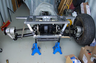
Other, more tangible progress has involved the assembly of the rear axle. I completed the hub assembly by fitting the drive shafts and these are a simple matter of bolting up the to the inboard brake discs. With these in place, I can start to look at rear wheel geometry (camber and toe). An initial assessment indicates that I will have to modify the shim arrangement already in place, but from other blogs, there is a knack it does not seem to be too onerous a task.
I also collected the steering rack and mounts from the kit manufacturer and mocked these up at the front of the chassis. The arms on the rack are too long so will have to be ‘adjusted’ (read set about with a hack saw) to allow the proper toe adjustment. I am also not too keen on the provided mounting straps so I will probably end up making replacement billet versions. I also collected the radiator (bespoke for this car) in the same trip to allow me to add the proper inlet and outlet positions to the CAD model for routing the cooling pipes as well as consider methods for mounting the fan.
Once the steering rack has been modified, I can look to carry out the initial wheel alignment - camber, castor and toe at the front along with camber and toe at the rear. I say initial as the full weight of the car on the wheels will tweak the settings, but it should get me quite close.


Hi, I've got a small but cheeky request, .I'm early stages of MK4 Jag based build but am going for side pipes because I'm awkward. I'd like to make or at least design
ReplyDeletemy own headers. I was going to ask if it would be possible to have a copy of your chassis cad model? As I said i know I'm bring cheeky, but it'll save a good chunk of time in modelling it here,
Cheers
Greg