Showing posts with label Suspension. Show all posts

Monday, 10 March 2014

Still chipping away!

Despite the distinct lack of updates, I have been making some progress on the build. Since my last missive, I have test run the CNC milling machine and for the most part was pleased with the result. I was able to successfully use the MeshCAM software to convert the 3D CAD model to G-Code (the language that the milling machine uses), run the spindle off the power supply that was recued out of a skip and the motion control (from PC signal to stepper motor drive) worked faultlessly. Unfortunately, there was an issue with the overall stiffness of the machine that meant the surfaces finish left a lot to be desired when cutting aluminium. I identified two major routes to improve the situation – one was to increase the torsional stiffness of the gantry, the other was the lateral stiffness of the bed. In addition, I have replaced the spindle motor with one which includes an integral cooling fan which will allow better continuous operation. These modifications have now all been completed and the second commissioning run is anticipated this week.

Other progress has been centred around the manufacturing method of the intake manifold. The manifold runners are essentially tubes of tapering cross sectional area, morphing from a rectangular to a circular cross section and sweeping around a path with a number of bends. Using conventional lamination methods would require two halves of the runner to be moulded, then joined (typically by a reinforced glue joint). I felt this was a risky strategy because the vibration, pressure pulsations and temperature loads may well lead to failure of this joint. I therefore needed a method of laying up a complete tube in one go. Despite my best google efforts, I have been unable to find someone who has published something similar so I have had to invent a method for making these parts. This involves a ‘lost wax’ lamination method where a sacrificial plug of wax is moulded then the continuously woven carbon fibre sleeve can then be laid up over it and consolidated with heatshrink tube. Once cured, the wax can be melted out of the part during the post-cure process of the resin.

The first job for the improved milling machine will therefore be to cut the plug that will be used in the carbon fibre runners in the intake manifold, but before I can do that, I needed to establish some shrinkage values. The wax I intend to use is typical paraffin wax used in candles which can have anything up to 3% shrinkage during cooling, this combined with the 0.5% shrinkage of the resin lay up and whatever method was used to cast the wax in the first place would have a noticeable effect on the finished part dimensions. I therefore decided to build a sample mould to measure the actual shrinkage, to be able to compensate in the plug dimensions. My chosen method for this was a ‘mother’ mould involving a silicone tooling layer, combined with a plaster outer shell for rigidity. I marked a piece of plastic rod with two grooves a know distance apart and created the mould. I could then pour molten wax into this mould and once cooled, measure the corresponding ridges in the silicone and grooves in the wax part. 


With the end grooves aligned, the shrinkage of the wax (on the right) can be seen against the original nylon (left).


The end result of all this was 0.5% shrinkage of the silicone, and 1.6% shrinkage of the wax. I also learned a couple of valuable lessons this moulding technique in that my original mould had insufficient keying between the two halves leading to a mis-match in the wax (I suspect a higher Shore hardness silicone would improve the situation), along with the need to pre-heat the mould before pouring the wax otherwise a poor surface finish results. Given the relative simplicity of the shape required, I have therefore decided to make the ‘production’ mould from a grade of casting plaster which will pre-heat well and the two halves can be made to lock together more effectively than the silicone. With the shrinkage values established, I should be machining the plug shortly, thought the finishing will take a little while longer as this will be inner surface of the runner and a good polished surface will help with overall performance.

As for the car itself, I have been wrapping up the last few jobs on the chassis assembly. On the rear axle, I have installed the springs and dampers, though these required a series of spacers to be machined due to clearances in the chassis bracket around the upper fixing.


The front springs and dampers are a simple case of bolting up to the waiting wishbones


Having the springs and damper allowed me to carry out the bump steer measurement and correction. A picture paints a thousand words, so a video must do that exponentially. I used method 3 (Rowly Method) as per the Pilgrim Sumo Wiki: measuring-bump-steer

I have cleaned and re-built the handbrake and attached the hand brake cable to the appropriate levers on the callipers.


In addition, I have procured the radiator cooling fan (a 16” unit from Kenlowe to be mounted behind the radiator) and fabricated the mounting brackets. These were simple pieces of sheet metal (laser cut for simplicity), folded, then 6mm bolts welded in (with their heads ground down to a minimum thickness). I have carried out a test fit, and will paint or powder coat them in due course.


Other chassis progress has been the procurement and fitting of the steering shafts and universal joints. The upper steering shaft needed the paint removing before the rose joint could be slid on and I need to wait until the complete column is fitted before establishing the final position of the support on the shaft. I will then be able to fix the rose joint and paint the remaining exposed steel.


The other big news is after much deliberation, sample trials and general indecisiveness, I have finally arrived at a specification for my body shell! I will be having the body in gel coat, partly for cost reasons, but mostly because the gel will be much thicker than any paint and therefore will be much more resistant to stone chips and easier to repair. I was not comfortable making a colour decision based on a small sample swatch, so ended up laying up a 12” square of each of the short list colours before the final decision. Unfortunately, you will all have to wait until the body is collected before you get to see the grand unveiling, but I should be in possession of the complete body within a few weeks. Can’t wait!

Monday, 4 February 2013

New Year, New Progress


First update of 2013 so happy new year to everyone!

Progress on the build has been sporadic at best but on the odd occasion where the planets aligned, I have managed to complete some aspects of the build. Chiefly among these is the suspension alignment. Jaguar in their infinite wisdom elected to provide for rear wheel alignment by the use of shims at the wishbone and drive shaft mounting points. This is fine in principal until you get to the part that requires half of the suspension to be disassembled to allow a shim to be added or removed. Inevitably during the reassembly the parts do not go back together exactly as previously and the expected change in alignment has not occurred.Still, I got into the swing of measurement, disassembly, adjustment,re-assembly (including lock wiring) and re-measurement to the point where two days work later, I have the rear wheels pointing in the correct direction! Front wheel alignment was considerably easier with the more convention threaded track rod ends requiring a couple of turns to bring everything into specification. Cue gratuitous shot of chassis with build wheels


Elsewhere on the car, I was not keen on the provided metal straps to fix the steering rack in place so I elected to machine replacements from billet aluminium. These have been fitted although I still have to measure bump steer which will likely require some adjustment of steering rack position.


I designed a bracket for the clutch slave cylinder including carrying out some analysis to ensure it would not fail form fatigue. Once the design and analysis was complete I could procure the required parts to make it. These (along with a plate for securing the gearbox tail housing) were laser cut from sheet steel and the tack welded into shape for a trial fit. Everything seemed to align as required so this can now be fully welded before painting.


Other progress includes forming the remaining brake hard lines both for the two front uprights and at the rear of the chassis for the rear brake callipers. This also required me to machine a spacer for the junction block so as to avoid the fuel hard lines vying for space in the same part of the car.


Lastly, I have trial fitted the radiator, partly start looking at cooling hose routing, but mostly getting it out of the way so I don’t accidentally kick a hole in it!


Monday, 19 November 2012

Slowly but surely

Holiday, other commitments and a short spell off due to injury means it been a while since there was any reportable progress on the Cobra, but I have still managed to keep some things ticking along.

I have progressed the intake manifold design where the major elements are at least in place in the CAD model. There is still some detailing to be done, but I believe there is enough in the scheme to suggest that the basic layout will work. 


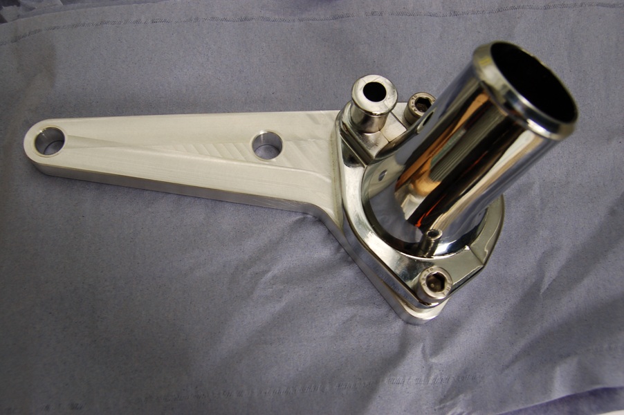
One area of concern I identified was around the thermostat housing neck as on the model, it looked a little too close to the alternator tensioner. Since it would be a while before the lower intake manifold (to which the water neck is bolted) is manufactured and to gain some confidence in that the elements of the CAD model bore some semblance to reality, I decided to manufacture a mock-up plate. 


This is bolted to the cylinder head but provides the opening that the manifold would, including the fixing positions and sure enough, there was a clash. 


At least I know this bit of the CAD model is reasonable! I have since found an alternative water neck and all seems well now.

Other, more tangible progress has involved the assembly of the rear axle. I completed the hub assembly by fitting the drive shafts and these are a simple matter of bolting up the to the inboard brake discs. With these in place, I can start to look at rear wheel geometry (camber and toe). An initial assessment indicates that I will have to modify the shim arrangement already in place, but from other blogs, there is a knack it does not seem to be too onerous a task.


 I also collected the steering rack and mounts from the kit manufacturer and mocked these up at the front of the chassis. The arms on the rack are too long so will have to be ‘adjusted’ (read set about with a hack saw) to allow the proper toe adjustment. I am also not too keen on the provided mounting straps so I will probably end up making replacement billet versions. I also collected the radiator (bespoke for this car) in the same trip to allow me to add the proper inlet and outlet positions to the CAD model for routing the cooling pipes as well as consider methods for mounting the fan.


Once the steering rack has been modified, I can look to carry out the initial wheel alignment - camber, castor and toe at the front along with camber and toe at the rear. I say initial as the full weight of the car on the wheels will tweak the settings, but it should get me quite close.


Monday, 16 July 2012

Donor Rebuild Part 2 - pivots


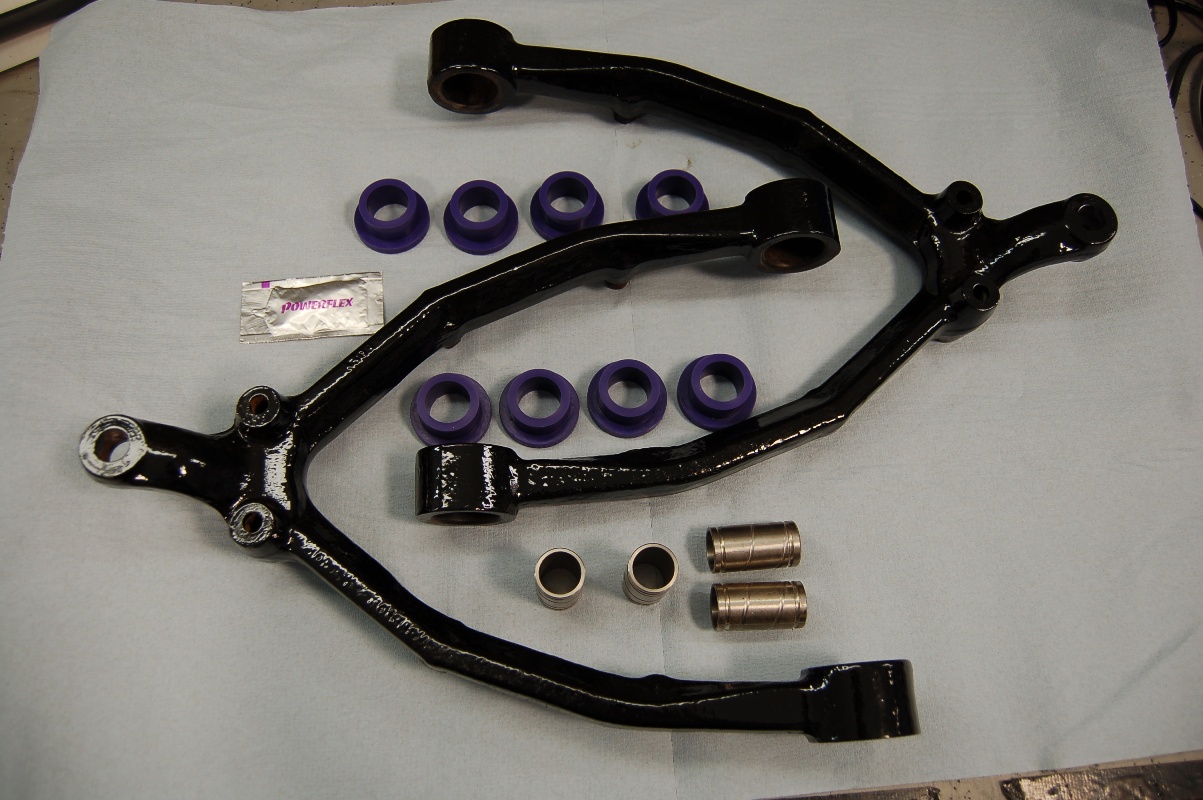
The big new is that I finally have a completion date of the chassis which will be ready by the end of this month. The donor brakes and differential are back from reconditioning and I am progressing the rebuild of the suspension components. To this end, I have been working on the lower front wishbones and fitted the replacement bushes


In addition, I have assembled the lower pivots on the rear uprights. This is a particularly involved process as there are two taper roller bearings which must be shimmed to achieve the required endfloat. This involves a dry build with a known thickness of shim pack in place and then the float of the bearings measured. Shims can then be removed to achieve the required clearance on the bearings. It then has to be dismantled to allow final assembly with the bearings packed with grease and the outer seals to be fitted. These are very ‘old school’ where a ring of felt material is used – this has to be soaked in engine oil for at least 24 hours to ‘load’ it with lubrication before a very messy installation. Still, this is now completed and it is all held together with a temporary retainer because the lower pivot shaft does the job in the final assembly, but this can only be fitted on the car.


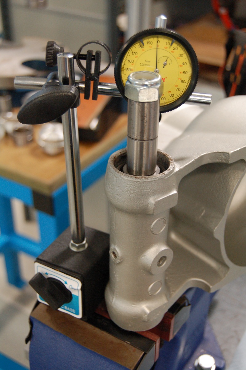
One last job remains on the rear uprights with setting the bearing clearances for the output flange. This has required a specific bit of tooling to be manufactured, but fortunately, I have access to a lathe to allow this. There is still some assembly, checking and shimming required on the differential which centres the brake discs in the callipers and sets the rear suspension geometry (camber and toe) however, this is more easily carried out as the parts are assembled to the chassis. Bring on the end of the month!

Monday, 9 May 2011

Oily and Greasy part 3

The lower rear wishbones represent the last of the donor suspension parts that I needed to clean and protect, so it was out with the wire brushes, and a fresh tub of elbow grease at the ready. These took some effort, mostly from their sheer size and weight, however they are fully cleaned and painted now.


Some replicas shorten the rear drive shafts and wishbones to give a more 'original' look to the rear wheel offset (deep dish on the rear wheels) however, most Gardner Douglas kits do not do this and mine will not be an exception. I still need to procure most of the bearings, spacers, shims, shields, washers and the other 101 parts that make up the working elements of the suspension, but for now I am happy that what I have is good to go into storage until needed.

The other source of grease and oil (the engine) has also received some attention. I purchased a cut-out short block which needed final disassembly and assessment for machining requirements. All was going well until I removed piston number 8 (actually, it fell out of the block once I had freed the big end – this was not a good sign!) Upon closer inspection, It appears that this piston had made a bid for freedom from the engine through the exhaust valve in the form of aluminium vapour. Apparently, it is a known fault with engines of this age in certain vehicle installations where part of the induction system becomes blocked, forcing cylinder 8 to run lean. If it is left unchecked, it gets to the point were detonation occurs which eventually melts the piston – this is what appears to have happened in my engine. The upshot of it all is that the remains of the oil ring scratching the nicely honed surface along with aluminium being smeared up and down the bore means a re-bore and new pistons all around. At least I had budgeted for this!


I now need to put together a shopping list of all the parts required to turn this into a fire-breathing Cobra power plant, along with a list of banks I might raid to pay for it all!

Tuesday, 19 April 2011

Oily and Greasy take 2

More rust stripping, cleaning and painting has occurred with the completion of the vast majority of the donor suspension parts.


One particularly stubborn output yoke proved a little difficult in separating it from its seal track, but access to more 'industrial' tools at work and they soon parted company. This along with the two lower rear wishbones represent the last steel suspension parts requiring the POR15 treatment. The rear uprights still need a good going over, but as they are aluminium they will require a different approach