Showing posts with label Megasquirt. Show all posts

Monday, 23 September 2013

Just like buses...

...nothing for ages, then two updates together!

Some of the smaller jobs ticked off the list most recently include finally finding a solution to the thermostat housing problem. Having bought two aftermarket versions (which although nice and shiny, did not fit), I thought I would throw caution to the wind an source a genuine Ford part. Low and behold it dropped straight in with no issues! The only modification I needed was to drill and tap the optional fitting in the top so I could fit a secondary temperature sensor. This will be the sensor to drive the temperature gauge whereas the sensor in the normal position in the manifold will be reserved for the Engine Control Module. It is possible I could have used a single sensor for both, but there were potential buffering and ground loop issues having two processors reading the same sensor so I thought in the interest of fault diagnosis, two was better than one.

Carrying on the sensor theme, I have sourced an oil pressure sensor that GM use on their LS series of engines, and machined up an adaptor to allow connector to the normal ‘idiot light’ switch position on the engine block. As usual, nothing is ever that simple, and clearance to the block meant that the sensor would not simply screw into the same position, so the adaptor also had to relocate the sensor to a remote location. Fortunately, Ford have provided a suitable threaded boss in the water pump for just such an occasion. A short braided hose was also required to connect the two together, so another skill of hose assembly was learned.


The other sensor fitted recently was to read oil temperature. Once again, Ford have been kind enough to provide an easy route in the form of a  secondary drain plug in the sump. This is used to get all of the oil out that would otherwise be trapped by the ‘hump’ of the oil pan that clears the sub frame normally running under the engine. I was able to reverse engineer the thread used on this fitting and machine up an adaptor for the sensor. It is not at the lowest point on the chassis but it is still a little vulnerable, so this will get some kind of skid pan to protect the connector and wiring.


Since the sensors will be read by a microprocessor, I have not been able to use the more typical 1-wire senders as the earth path through the block typically affects the measurements. I have therefore had to use 2-wire sensors which are more difficult to come by, and even harder to find suitable data sheets. Fortunately, the GM LS engines are used quite a lot in aftermarket installations (they will sell a whole crate engine if you want), and more data is available on the spares. I therefore have a Ford engine, but controlled and monitored using GM sensors – fingers crossed they will work together without getting into a fight!

Other progress has been the fitting of the clutch slave cylinder and making up the braided hose for the hydraulic line and I have now collected the rear part of the exhaust from Gardner Douglas. This connecting pipes will need modifying (or replacing) to meet up with my own design headers, but it gives me a head start in terms of known good routing under the chassis and bodywork.


As for the milling machine, I have now connected the motors to the various slides and successfully run through a sample program. There are a couple of parts to finish on the spindle drive and I will then be in good shape to start test cutting.

Monday, 7 November 2011

Virtual Cobra Build

With another batch of engine parts delivered, I have been progressing the block build up although missing a couple of vital items off the order means I am not as far as I could have been! Still, it gives me the chance to prepare the parts properly while I wait so I have colour matched the timing cover and water pump to the block.

In addition, I have been working on the installation of a vital part of the fuel injection system – the crank position sensor. Since the stock version of this part is prohibitively expensive to buy new and there aren’t many Mustangs in scrap yards around here, I have bought a more readily available standard component and designed a combined bracket and timing pointer along with a suitable trigger wheel.


Other ‘virtual’ progress has been around the design of the instruments and I have decided that an illumination test is required before committing to a proper PCB. I therefore need to mock up the instrument face and back lighting to ensure I have sufficient brightness to meet the Individual Vehicle Approval (IVA) test requirements. To this end I have designed a first pass circuit (which I should be able to build at work thanks to the prototype PCB facility here at work) and a ‘mask’ to direct the light. This is designed to be water jet cut along with the timing pointer components and some other instrument parts so I am aiming to group these together and procure them in the near future. Once these are in, I can build and test a number of aspects of the design before finalising the board design and getting it manufactured properly.


Wednesday, 7 September 2011

Megaflash

With a recent bout of extra hours at work have been a double edged sword – on one hand I have not had the time or energy to work on the Cobra much, but on the other it has boosted the funding! I have therefore been able to procure a significant set of parts from the US that are otherwise difficult or impossible to source in the UK. These include:
  •  A pair of aftermarket aluminium cylinder heads and head bolts
  • Roller cam shaft and lifters suitable for a fuel injected engine
  • A set of roller rocker arms
  • Cam position sensor housing (which normally replaces the distributor, but I will use only as an oil pump drive)
  • Appropriate head and port gaskets
  • Pushrod length checking tool
  • Billet piston ring compressor 
The main job with most of these parts is to digitise them so I can build up the engine CAD model in preparation for the manifold design – I’d better get out the measuring stick then!


Other progress has finally seen the completion of the Engine Control Unit customisation. I built the basic Megasquirt kit a while ago and combined all of the modifications that I wanted onto a custom designed auxiliary Printed Circuit Board. I have now finished incorporating this extra PCB into the enclosure and have successfully bench tested the system using an electronic ‘stimulator’ to mimic the engine signals and loads. My additions over the basic assembly are:


  • 4 coil drivers for wasted spark ignition
  • 5V square wave output tachometer signal
  • Second wide-band Exhaust Gas Oxygen (EGO) sensor input
  • Open collector ‘engine running’ signal to disable starter motor
  • Relay driver to control radiator fan


With these additional functions operational (well, flashing a bunch of LEDs on the stimulator board!), I can now move on to building up a hardware test bench to run the actual engine components (coils, injectors etc.) before attempting to control an actual engine.

Tuesday, 29 March 2011

Oil and Grease Free

Despite my lack of updates, I have not been idle on my Cobra project. I have mostly been working on the 'cleaner' aspects of the job, concentrating on some of the electronics I will be using. First off, I finished the Megasquirt auxiliary board and since it was a two layer (top and bottom copper) layout, I have had it made by one of the many PCB prototyping houses. This was recently delivered:


A quick check in the enclosure with the vehicle connector in place:


Now all I need to do is solder it up and give it a test!

In addition, I have been developing the vehicle electrical system and have decided on at least trying to build my own electrical modules. These will cover the instruments, direction indicators and heating controls. So far I have identified the use of a Picaxe Programmable Integrated Chip (PIC) as supplied by Revolution Education. These have a simple BASIC programming laguage and are used for a whole host of projects, mostly by hobbyists. This system will allow me to control the blower and heater solenoid valve, flash the indicators and drive instrument stepper motors, and display information such as miles covered and ambient temperature. A lot of work will be required to get these moduiles up and running, but I think they will be worth it in the end.

Wednesday, 22 December 2010

Megasquirt Aux Board

I have now installed the output stage comprising the injector, fuel pump and Air Bypass Valve (ABV) drivers and this marks the completion of the base Megasquirt controller. However, the extras I am adding (Automotive connector, 2 coil pack wasted spark control, radiator fan control, tachometer output pulse, 2nd Exhaust Gas Oxygen sensor input, and 'engine running' signal) require an additional circuit board. I have tracked down what appears to be a relatively easy to set up and use PCB generation tool called Designspark. So far I have created the auxiliary board schematic:


Which then allowed me to create the PCB layout:


There are still a couple of details I need to sort out such as the flyback diodes for the relay driver and ABV, but I should be in a position to send this board for manufacture shortly. Before I do though, I would like to prototype some of the circuits just to make sure it will all work as planned!

Friday, 10 December 2010

Megasquirt Episode 3 - Revenge of the Sith

Progress has continued on the engine controller with the construction of the power stage with the required testing showing volts where they need to be and no volts where they shouldn't. Since I am not using the standard Megasquirt DB-37 connector, I am having to temporarily connect using discrete wires. Ultimately these will to be replaced with a flying lead to the auxiliary board containing the additional components for the wasted spark coil drive, tachometer output signal and the second exhaust gas oxygen (EGO) conditioning circuit.


The communication components are added next and checked for correct function thorough the programming connector.


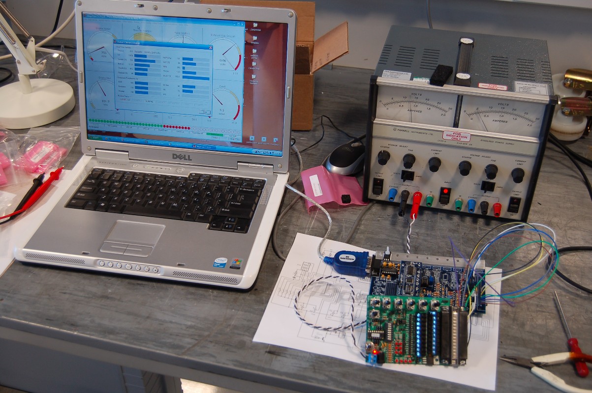
With the board working according to the instructions, I was able to move onto the input conditioning circuits which take the engine sensor data and feed it into the main processor inputs. With these components in place, I could hook it up the the laptop and run the Megatune software used for communicating with, and tuning the ECU.


The engine sensors are replicated by the Stimulator so the pots can be twiddled and the corresponding reading on the real time display changes. So far so good...

Thursday, 2 December 2010

MegaStart - The Sequel

Following successful testing of the JimStim (well, making sure there was 12V where it should be and resistances change with twiddling the pots) I made a start on building the Megasquirt module proper. The comprehensive kit from DIY Autotune comes extremely well packaged and labelled, identifying each component, its value and important assembly information such as leg bend length and if the part needs to stand off from the PCB. I would heartily recommend this company to anyone considering the purchase of a kit, or indeed anything related. Anyway, I had to make a start on this:


First job was a modification (I can't do anything the conventional way!). I am planning to use wasted spark, PWM Idle valve control, ECU controlled cooling fan relay and an 'engine running' signal, so it seemed logical to have an auxiliary PCB to tidy everything up. In addition, I am not keen on soldering wires into connectors for automotive applications since there is a risk, albeit small, of wire breakage from fatigue. The standard solder bucket DB37 connector will have to be replaced with an automotive spec crimped terminal part. I managed to stumble across an enclosure of similar footprint, but taller to allow all of the additions to be made so I procured it from Maplin (part number N85AL) and set about scheming the design. Fortunately, the enclosure manufacturer kindly makes 3D CAD models available, so this was a relatively easy job:


With this complete, I could make a start on trying to turn it into reality. Since the enclosure is metric (100mm wide slot opening) and the Megasquirt PCB is imperial (4 inches), I had a small amount of filing to get the two to mate together. This had to be done with great care to ensure the intermediate copper layers (it is a 4 layer PCB) were not shorted to the case. All appeared to be well:


This has a knock-on effect to the heatsink strip that sits under the power devices. I had to shave a small amount off this as well to get the holes to line up:


With this all fitting together, I can make a start on stage 1 of the controller - the power supply.

Tuesday, 30 November 2010

MegaStart

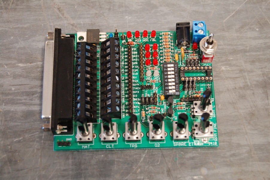
With the arrival of my fuel injection controller kit (Megasquirt), I have turned my attention to my soldering iron. The first task is to build the 'stimulator' which is a unit that replicates the engine signals allowing you to test the Megasquirt ECU during and after its construction. There are two readily available options - the Megastim from the people who designed the ECU, and the one I opted for - the JimStim v1.5. The advantages for me are that the JimStim includes a chip that simulates the trigger wheel output I will be using (36-1 teeth) as well as a breakout block to allow the real sensors and signals to be wired into the system. This means I can test the ECU purely on the Simulator and then introduce the real engine hardware one piece at a time. Fault finding should be a little easier (I hope!). Before all that can happen, though I needed to turn this:


With a flurry of flux smoke and singed fingers, into this:


Now if only there were some kind of device I could use to test the stimulator, all would be well!


Thursday, 25 November 2010

Intake Manifold - The beginning

The aftermarket fuel injection controller I will be using (Megasquirt II) is typically set up to be a speed-density system meaning the computer measures the engine speed and manifold pressure, then calculates the mass air flow into the cylinders. The injected fuel is then a proportion of that air mass to achieve the desired air : fuel ratio (nominally 14.7:1, but varies with operating conditions). Closing the loop with a lambda sensor in the exhaust stream confirms the desired ratio is achieved and if not, some 'live' tweaking can occur. This system works well, but is based on the assumption that the total air flow is evenly split between the cylinders. This is where the intake manifold comes in, as it is critical to splitting and delivering the air charge to the individual cylinders. There are a couple of options for a fuel injected manifold on the Ford 302; use a late model stock system or modify an standard carburettor manifold with injector 'bungs'. The appearance of the stock system is not really in-keeping with the look I want for the engine bay and I have concerns over how well the air will be distributed with the carb manifold (either single or dual plane). To allay (or confirm!) those concerns, I have decided to do some investigation work which involves some engineering analysis. Fortunately, I have access to a CAD workstation with CFD (Computational Fluid Dynamics) software and I will be looking at comparing the performance of the options for my intake manifold.

Watch this space...