Showing posts with label Chassis. Show all posts

Monday, 10 March 2014

Still chipping away!

Despite the distinct lack of updates, I have been making some progress on the build. Since my last missive, I have test run the CNC milling machine and for the most part was pleased with the result. I was able to successfully use the MeshCAM software to convert the 3D CAD model to G-Code (the language that the milling machine uses), run the spindle off the power supply that was recued out of a skip and the motion control (from PC signal to stepper motor drive) worked faultlessly. Unfortunately, there was an issue with the overall stiffness of the machine that meant the surfaces finish left a lot to be desired when cutting aluminium. I identified two major routes to improve the situation – one was to increase the torsional stiffness of the gantry, the other was the lateral stiffness of the bed. In addition, I have replaced the spindle motor with one which includes an integral cooling fan which will allow better continuous operation. These modifications have now all been completed and the second commissioning run is anticipated this week.

Other progress has been centred around the manufacturing method of the intake manifold. The manifold runners are essentially tubes of tapering cross sectional area, morphing from a rectangular to a circular cross section and sweeping around a path with a number of bends. Using conventional lamination methods would require two halves of the runner to be moulded, then joined (typically by a reinforced glue joint). I felt this was a risky strategy because the vibration, pressure pulsations and temperature loads may well lead to failure of this joint. I therefore needed a method of laying up a complete tube in one go. Despite my best google efforts, I have been unable to find someone who has published something similar so I have had to invent a method for making these parts. This involves a ‘lost wax’ lamination method where a sacrificial plug of wax is moulded then the continuously woven carbon fibre sleeve can then be laid up over it and consolidated with heatshrink tube. Once cured, the wax can be melted out of the part during the post-cure process of the resin.

The first job for the improved milling machine will therefore be to cut the plug that will be used in the carbon fibre runners in the intake manifold, but before I can do that, I needed to establish some shrinkage values. The wax I intend to use is typical paraffin wax used in candles which can have anything up to 3% shrinkage during cooling, this combined with the 0.5% shrinkage of the resin lay up and whatever method was used to cast the wax in the first place would have a noticeable effect on the finished part dimensions. I therefore decided to build a sample mould to measure the actual shrinkage, to be able to compensate in the plug dimensions. My chosen method for this was a ‘mother’ mould involving a silicone tooling layer, combined with a plaster outer shell for rigidity. I marked a piece of plastic rod with two grooves a know distance apart and created the mould. I could then pour molten wax into this mould and once cooled, measure the corresponding ridges in the silicone and grooves in the wax part. 


With the end grooves aligned, the shrinkage of the wax (on the right) can be seen against the original nylon (left).


The end result of all this was 0.5% shrinkage of the silicone, and 1.6% shrinkage of the wax. I also learned a couple of valuable lessons this moulding technique in that my original mould had insufficient keying between the two halves leading to a mis-match in the wax (I suspect a higher Shore hardness silicone would improve the situation), along with the need to pre-heat the mould before pouring the wax otherwise a poor surface finish results. Given the relative simplicity of the shape required, I have therefore decided to make the ‘production’ mould from a grade of casting plaster which will pre-heat well and the two halves can be made to lock together more effectively than the silicone. With the shrinkage values established, I should be machining the plug shortly, thought the finishing will take a little while longer as this will be inner surface of the runner and a good polished surface will help with overall performance.

As for the car itself, I have been wrapping up the last few jobs on the chassis assembly. On the rear axle, I have installed the springs and dampers, though these required a series of spacers to be machined due to clearances in the chassis bracket around the upper fixing.


The front springs and dampers are a simple case of bolting up to the waiting wishbones


Having the springs and damper allowed me to carry out the bump steer measurement and correction. A picture paints a thousand words, so a video must do that exponentially. I used method 3 (Rowly Method) as per the Pilgrim Sumo Wiki: measuring-bump-steer

I have cleaned and re-built the handbrake and attached the hand brake cable to the appropriate levers on the callipers.


In addition, I have procured the radiator cooling fan (a 16” unit from Kenlowe to be mounted behind the radiator) and fabricated the mounting brackets. These were simple pieces of sheet metal (laser cut for simplicity), folded, then 6mm bolts welded in (with their heads ground down to a minimum thickness). I have carried out a test fit, and will paint or powder coat them in due course.


Other chassis progress has been the procurement and fitting of the steering shafts and universal joints. The upper steering shaft needed the paint removing before the rose joint could be slid on and I need to wait until the complete column is fitted before establishing the final position of the support on the shaft. I will then be able to fix the rose joint and paint the remaining exposed steel.


The other big news is after much deliberation, sample trials and general indecisiveness, I have finally arrived at a specification for my body shell! I will be having the body in gel coat, partly for cost reasons, but mostly because the gel will be much thicker than any paint and therefore will be much more resistant to stone chips and easier to repair. I was not comfortable making a colour decision based on a small sample swatch, so ended up laying up a 12” square of each of the short list colours before the final decision. Unfortunately, you will all have to wait until the body is collected before you get to see the grand unveiling, but I should be in possession of the complete body within a few weeks. Can’t wait!

Monday, 19 November 2012

Slowly but surely

Holiday, other commitments and a short spell off due to injury means it been a while since there was any reportable progress on the Cobra, but I have still managed to keep some things ticking along.

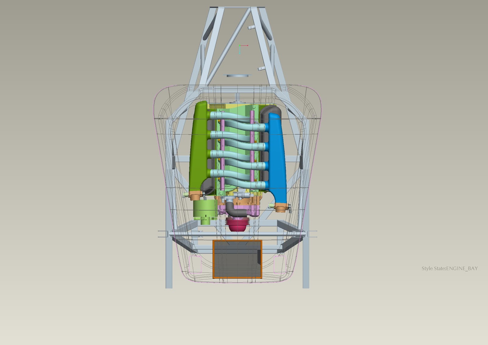
I have progressed the intake manifold design where the major elements are at least in place in the CAD model. There is still some detailing to be done, but I believe there is enough in the scheme to suggest that the basic layout will work. 


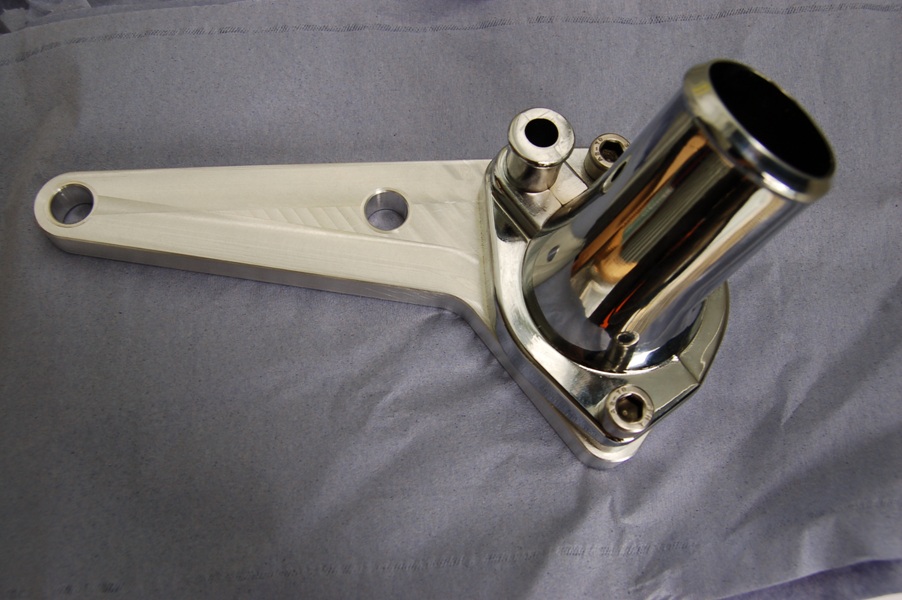
One area of concern I identified was around the thermostat housing neck as on the model, it looked a little too close to the alternator tensioner. Since it would be a while before the lower intake manifold (to which the water neck is bolted) is manufactured and to gain some confidence in that the elements of the CAD model bore some semblance to reality, I decided to manufacture a mock-up plate. 


This is bolted to the cylinder head but provides the opening that the manifold would, including the fixing positions and sure enough, there was a clash. 


At least I know this bit of the CAD model is reasonable! I have since found an alternative water neck and all seems well now.

Other, more tangible progress has involved the assembly of the rear axle. I completed the hub assembly by fitting the drive shafts and these are a simple matter of bolting up the to the inboard brake discs. With these in place, I can start to look at rear wheel geometry (camber and toe). An initial assessment indicates that I will have to modify the shim arrangement already in place, but from other blogs, there is a knack it does not seem to be too onerous a task.


 I also collected the steering rack and mounts from the kit manufacturer and mocked these up at the front of the chassis. The arms on the rack are too long so will have to be ‘adjusted’ (read set about with a hack saw) to allow the proper toe adjustment. I am also not too keen on the provided mounting straps so I will probably end up making replacement billet versions. I also collected the radiator (bespoke for this car) in the same trip to allow me to add the proper inlet and outlet positions to the CAD model for routing the cooling pipes as well as consider methods for mounting the fan.


Once the steering rack has been modified, I can look to carry out the initial wheel alignment - camber, castor and toe at the front along with camber and toe at the rear. I say initial as the full weight of the car on the wheels will tweak the settings, but it should get me quite close.


Tuesday, 28 August 2012

Let the games begin

A bumper update this week thanks to the long weekend. Since receiving the chassis and borrowing a spare bonnet from the kit manufacturer, I have been working away at creating a CAD model. This was finished up to the necessary level ahead of the weekend so I could break out the tools and start building!


The build manual recommends assembling the rear axle off the chassis, then lowering the framework around it. This seemed like a sensible approach, so I made it the first task as manoeuvring a bare chassis sounded easier than moving a partially assembled one. The rear axle is straight out of the donor Jaguar with the lower wishbones pivoted off the differential. This means that the pivot mounting brackets determine the toe and thrust of the rear wheels and have to be carefully aligned with shims. The brackets that hold the assembly into the chassis are drilled to provide the correct alignment (in theory), so I set about mocking up the pivots to determine the correct shims. I will still have to measure the alignment when the axle is complete to finally check the toe and thrust measurements, but this should give me a good start. 


With the shims established, I could fix the lower pivot brackets and make my first attempt at lockwiring the bolt heads, which proved easier than anticipated (when you wrap the wire the correct way around the bolt head!).


 The rest of the rear axle assembly continued as per the Haynes (Chilton) manual including shimming of the rear brake discs (rotors) to centralise them in the callipers and assembly of the rear brake callipers. The assembly of the inner pivot tubes proved to be fun thanks to the multitude of spacers, thrust washers and seal retainers, but the liberal application of grease held everything together long enough to assemble the pivot shaft without a pile of bits on the floor!


At this stage, the driveshafts and rear uprights would be fitted, but as I am still waiting on parts to complete their assembly, I moved on to fitting what I had to the chassis. This was simply a case of lowering the rear of the frame over the assembly and fitting 8 bolts.


With the rear assembly as complete as I could make it, I moved onto preparation for engine installation. This involved fitting the two fuel lines (feed and return for the injection system) along with the brake pipes. The fuel lines were installed using brackets I designed and a work colleague machined for me (thanks Colin), held in with rivnuts. 


The brake lines use a series of push-in clips and these (along with the fuel line clamps) have to be spaced to provide sufficient support as this is inspected at the Individual Vehicle Approval (IVA) test. Most of the fitting was relatively straightforward, however the front brake pipe proved more challenging due to the tortuous route under the engine mounting bracket. Two sore thumbs later and I was ready to fit the engine and gearbox assembly.


The chassis design allows for excellent access for this job and the only hindrance was a lack of manoeuvring space for the engine crane. It turned out to be easier to lift the engine up and slide the chassis under it before rolling the crane (and engine) into place. The engine mounts were bolted into place and the powertrain was in its new home. The gearbox tail housing is currently sat on a piece of wood until I can fabricate the rear mounting bracket.


With the engine installed, I was able to turn my attention to the front suspension. As per the rear axle, this is lifted straight from the Jaguar donor and bolts up to the chassis in the same way. The only real deviation is the bespoke steering arm to suit the new rack as well at the omission of the various shields. This concluded my weekend of construction – not bad for a few days work!


There is still some work to complete the front suspension assembly – making up a new pair of rigid brake pipes from the calliper to the flexible hose as well as setting up the front angles – camber, castor and toe. The geometry will be much easier to work on when I have the steering rack so this will have to wait for suitable funds! At least I can amuse myself with designing the intake system in the mean time.

Monday, 6 August 2012

Here's Chassis!

Big news – the chassis has finally arrived! Some last minute issues with the powder coating meant that is had to be stripped and re-applied twice and readiness for this Saturday’s collection was looking doubtful, but the sub contractor managed to finish it just in time.


I arrived at Gardner Douglas just as Andy was fitting the last of the rivnuts so timing was impeccable in the end. Andy was also good enough to lend me some donor Jaguar wheels to get me rolling in advance of the proper Halibrand replicas being purchased. I was also able to borrow a spare bonnet (‘hood’ to subscribers across the pond) for digitising into the computer to help with the induction system design. Not much else to say really – I am itching to start assembling the donor parts onto the chassis, but first job is to create a reasonably accurate CAD model of it to allow (in the first instance) the exhaust design to be carried out.

Monday, 30 April 2012

Chassis Ordered

Short post but big milestone. I visited Gardner Douglas and was made very welcome by Andy and Meena. It has been a while since I went on a 'scouting trip' whilst deciding on which kit to purchase, so I had another look around and a good discussion on the options and detail of my build. The upshot of it all is that I placed a deposit for a chassis, and I am officially in the production schedule. Roll on 8 to 10 weeks!