Showing posts with label Donor. Show all posts

Monday, 30 July 2012

Donor Rebuild Part 3


Chassis collection is now less than a week away, so I have been concentrating on the donor component rebuild in preparation. The lower rear wishbone has two pairs of needle roller bearings for the inner pivot and these are a light press-fit into the respective bores. The gap between each pair is to allow for a grease fitting on the outside to be used during servicing and a sleeve is used to provide the running surface.


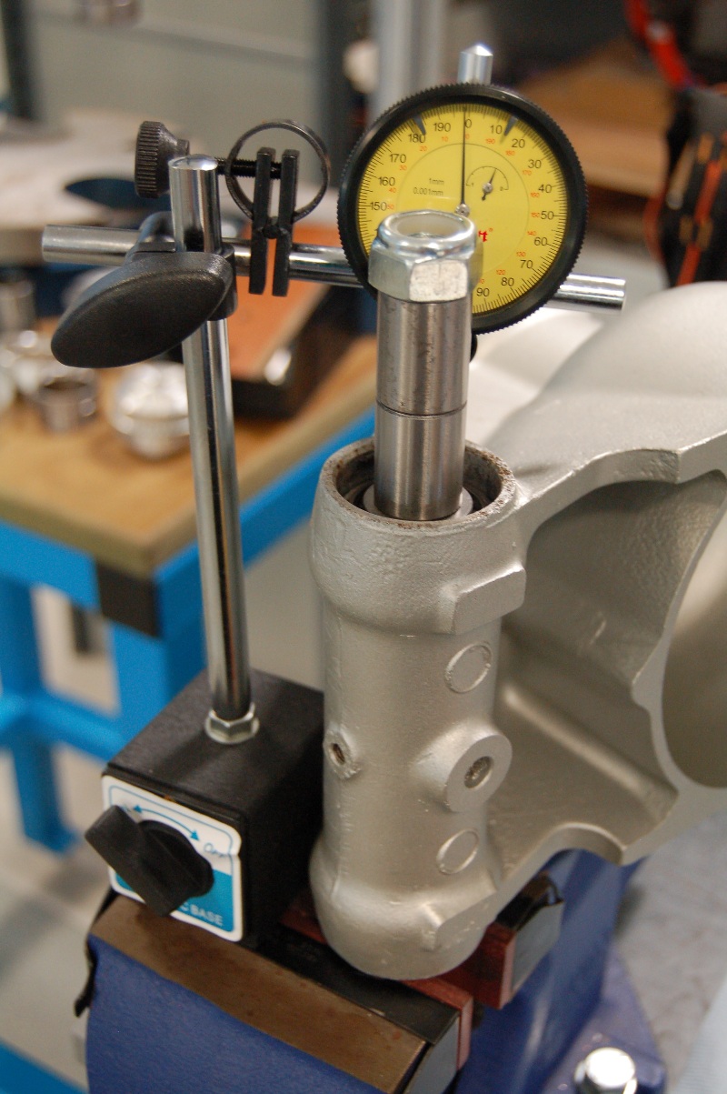
The final job on the rear uprights is the installation of the wheel bearings. As per other parts of the original car, the bearing clearance is controlled with spacers. In this case, the bearing has to be pressed into place with a known thickness spacer and the clearance measured. The target clearance can then be achieved by selecting a slightly thinner spacer of the correct thickness. The final bearing clearance is achieved by installing the driveshaft through the middle with the correct spacer in place and fully tightening the hub nut. Before this can be carried out though, the inner seal needs to be pressed in place.


Monday, 16 July 2012

Donor Rebuild Part 2 - pivots


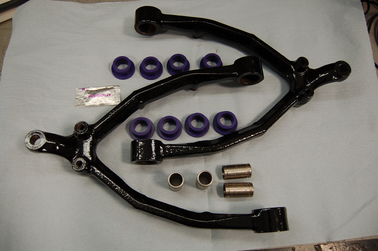
The big new is that I finally have a completion date of the chassis which will be ready by the end of this month. The donor brakes and differential are back from reconditioning and I am progressing the rebuild of the suspension components. To this end, I have been working on the lower front wishbones and fitted the replacement bushes


In addition, I have assembled the lower pivots on the rear uprights. This is a particularly involved process as there are two taper roller bearings which must be shimmed to achieve the required endfloat. This involves a dry build with a known thickness of shim pack in place and then the float of the bearings measured. Shims can then be removed to achieve the required clearance on the bearings. It then has to be dismantled to allow final assembly with the bearings packed with grease and the outer seals to be fitted. These are very ‘old school’ where a ring of felt material is used – this has to be soaked in engine oil for at least 24 hours to ‘load’ it with lubrication before a very messy installation. Still, this is now completed and it is all held together with a temporary retainer because the lower pivot shaft does the job in the final assembly, but this can only be fitted on the car.


One last job remains on the rear uprights with setting the bearing clearances for the output flange. This has required a specific bit of tooling to be manufactured, but fortunately, I have access to a lathe to allow this. There is still some assembly, checking and shimming required on the differential which centres the brake discs in the callipers and sets the rear suspension geometry (camber and toe) however, this is more easily carried out as the parts are assembled to the chassis. Bring on the end of the month!

Monday, 28 May 2012

Donor Rebuild Part 1

With the chassis on order as well as the differential and brakes out for reconditioning, I have turned my attention to the suspension components. I cleaned and painted these some time ago before putting them into storage and now was the time to dust them off and start reassembly. Every serviceable part (bearings, bushes seals etc.) is being replaced so after wading through various Jaguar parts catalogues, I have procured the vast majority of required components. No doubt shortfalls will be found as I progress, but I have at least been able to make a start:

First up are the drive shafts (which also double as the upper rear 'wishbones'). These are each a 3-piece affair with universal joints connecting each section


Next up, the front uprights. When I originally disassembled these, the stub shafts were quite badly worn at the wheel bearing locations, so new ones were purchased


The front hubs get new bearings and seals along with replacement dust shields for good measure


Finally, for this update, the front upper wishbones. I have chosen to go with polyurethane bushes to replace the original rubber items from Jaguar. There is some contention on the use of these on the Cobra Club forum, but the majority of people use them, so I figure its a good starting point and it is not too onerous to replace them after the vehicle is up and running (if that ever happens!)


Monday, 23 January 2012

Engine build continues

It has been some time since my last update, mainly because it has been some time since I made any progress. However, the planets aligned this weekend and I hade the time available, the appropriate tools to hand and most importantly, the weather smiling on me so I could continue the engine build.

First task was to measure the endfloat of the camshaft and crankshaft as these values are critical for proper lubrication.


Pressing my new Dial Test Indicator (DTI) into service, I was able to check that these measurements were within specification and so could move onto ‘degreeing’ the camshaft. For those unfamiliar with the job, this means checking the cam timing against the crank angle and involves fitting an angle gauge to the crank (aligned with number 1 piston) and measuring the angle of maximum lift of the corresponding intake and exhaust tappets (lifters). These angles may not be quite as the manufacturer intended due to component tolerances of the specific engine being built and there is an amount of adjustment in the system to allow for compensation.

My cam timing came out to be around 1.5 degrees late, but since the three adjustment positions I had available it 0, +4 degrees or -4 degrees (I have not seen a vernier cam sprocket for these engines that will fit under the stock timing cover), this was a close as I was going to get! Next up was fitting the oil pump which needed modification in order for the mounting bolts to sit flat. Fortunately, the milling machine at work had been available for such a job and made light work of the task.


Fitting the oil pickup pipe finished off that part of the assembly and with one last torque check of the bolts, I could move onto closing up the oily bits of the engine.This started with the timing chain cover then the sump followed by the water pump. These were relatively simple tasks, but since I am using a random collection of original equipment, reproduction and aftermarket parts, some of the fastener kits don’t have the correct bolts so I need to purchase some additional hardware before I can finish this off.


I am now at the stage where I need to procure the parts I have designed for adding the fuel injection components before I can progress the engine build any further. I suspect it may be a little while before the planets align again, so it is not too much of a rush!

Monday, 17 October 2011

Engine build up - part 1

With a recent bout of reasonable weather, I have been able to start assembling the bare block back into a short engine. First job was to install the cam bearings which required a quick measurement of the bores before using my home made tooling to wind them in.


It was a little tricky at first, but by the time I got to the last bearing, I had it down to a fine art! With these installed, I could lubricate the cam and slide it home as this is an easier operation without the crank in position.


Next up was the crank itself starting with the main bearings and I checked the actual oil clearance using plastigauge (a first for me!). With all well and the crank spinning freely, I could move onto the pistons. A couple of the new rings needed filing to get the correct end gap, but for the most part they dropped in without hassle, forming the short block.


With the amount of machining carried out on the block, along with aftermarket heads and tappets (‘lifters’ for the subscribers on the other side of the Atlantic) I am unable to rely on the stock pushrod length being correct. I have therefore procured an adjustable pushrod which I used to check the required length. This involved marking the tops of two valves and mocking up the top end then turning the engine through one complete cycle. This leaves a witness mark on the end of the valves which needs to be centred across the tip. The adjustable pushrod is wound in or out to centre the mark then the process is repeated and checked for a pair of valves (intake and exhaust) on each cylinder head. Now I have determined the required pushrod length, I can go ahead with purchasing them and the full engine build can continue.


In addition to this, I have been creating a CAD model of the engine as accurately as I can which will aid me in the design of the intake and exhaust manifolds. I currently have a virtual engine in a similar state to the real one as the two need to be built in parallel. The key part missing at the moment is a rocker cover model as this will determine the location of the intake manifold plenums and routing of the corresponding tracts. I will be procuring this part along with the pushrods to help progress this part of the build.


Monday, 9 May 2011

Oily and Greasy part 3

The lower rear wishbones represent the last of the donor suspension parts that I needed to clean and protect, so it was out with the wire brushes, and a fresh tub of elbow grease at the ready. These took some effort, mostly from their sheer size and weight, however they are fully cleaned and painted now.


Some replicas shorten the rear drive shafts and wishbones to give a more 'original' look to the rear wheel offset (deep dish on the rear wheels) however, most Gardner Douglas kits do not do this and mine will not be an exception. I still need to procure most of the bearings, spacers, shims, shields, washers and the other 101 parts that make up the working elements of the suspension, but for now I am happy that what I have is good to go into storage until needed.

The other source of grease and oil (the engine) has also received some attention. I purchased a cut-out short block which needed final disassembly and assessment for machining requirements. All was going well until I removed piston number 8 (actually, it fell out of the block once I had freed the big end – this was not a good sign!) Upon closer inspection, It appears that this piston had made a bid for freedom from the engine through the exhaust valve in the form of aluminium vapour. Apparently, it is a known fault with engines of this age in certain vehicle installations where part of the induction system becomes blocked, forcing cylinder 8 to run lean. If it is left unchecked, it gets to the point were detonation occurs which eventually melts the piston – this is what appears to have happened in my engine. The upshot of it all is that the remains of the oil ring scratching the nicely honed surface along with aluminium being smeared up and down the bore means a re-bore and new pistons all around. At least I had budgeted for this!


I now need to put together a shopping list of all the parts required to turn this into a fire-breathing Cobra power plant, along with a list of banks I might raid to pay for it all!

Tuesday, 19 April 2011

Power

It was a big day yesterday with the collection of my Cobra's powerplant core - the engine. To call it an engine is a bit of a stretch since it is a short block (block, camshaft, crankshaft, pistons and con rods) however, since everything missing (and even some of the things fitted) will be replaced with new, it saves me the job of stripping down and scrapping the rest of the engine. The all important casting numbers on the side of the block indicate it was cast week 26 of 1993 which is just what I was looking for:

  • This age of engine has a one-piece rear crank seal which is better leak free solution
  • The crank has 50oz external unbalance which makes finding a flywheel for it marginally easier
  • It has a roller lifter camshaft of which there are more fuel injection friendly cam profiles available
  • The emissions test it will eventually have to pass during its IVA (individual Vehicle Approval) test has non-catalytic converter emissions limits. I therefore do not need to purchase and install cats in the exhaust system saving time, effort and cash!


From here, I need to finish stripping it down and assess just how much machining is required. At the very least I will be likely zero decking it (to raise the compression ratio), and boring it to remove the current wear marks. A decision on crank grinding will have to wait until I can measure the journals, but the general condition of the working parts suggest this may not be necessary.

Oily and Greasy take 2

More rust stripping, cleaning and painting has occurred with the completion of the vast majority of the donor suspension parts.


One particularly stubborn output yoke proved a little difficult in separating it from its seal track, but access to more 'industrial' tools at work and they soon parted company. This along with the two lower rear wishbones represent the last steel suspension parts requiring the POR15 treatment. The rear uprights still need a good going over, but as they are aluminium they will require a different approach

Tuesday, 29 March 2011

Oily and Greasy

To balance my work on the nice and clean circuit design and software writing, I decided to get some muck work under way. To this end I have started reconditioning the donor parts. The first task is to strip it all down and clean up, then protect with a suitable finish. The donor parts came from the scrap yard in major chunks which required final disassembly.


Front upright assembly as supplied from the scrap yard
After a flurry of activity with hammers, sockets and a handy press, I reduced it to its component parts:


Some people choose to grit blast and powder coat, but many use the POR15 system so I thought I would give it a try. The process requires the loose rust removing, then a good clean with 'Marine Clean' followed by a coat of 'Metal Ready' to neutralise the rust and provide a zinc phoshpate coat. Finally, two coats of POR15 and you are finished. If the parts are to be exposed to direct sunlight, a UV barrier is recommended. Since these are suspension parts, I don't need to worry about that.

I set about cleaning the rust and grease off using wire wheels and paint srtipping wheels in my drill. Once reasonably clean, I could move onto applying the POR15 system. The paint covers well and the scond coat was applied when the first was 'dry with a slight finger drag' as required by the instructions. I trialled the system on the two front lower wishbones and two front uprights:


It seems to have gone reasonably well, so I need to press on with the remaining donor parts